
The mmg2d application allows to discretize and optimize an implicitly defined surface (which means a surface defined by a level-set function). You can find more informations about the used algorithm here.
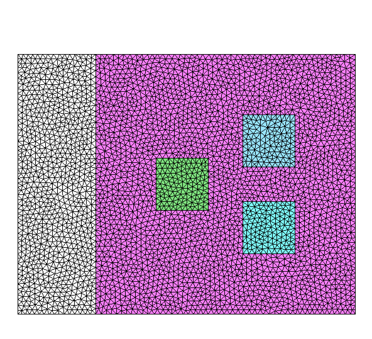
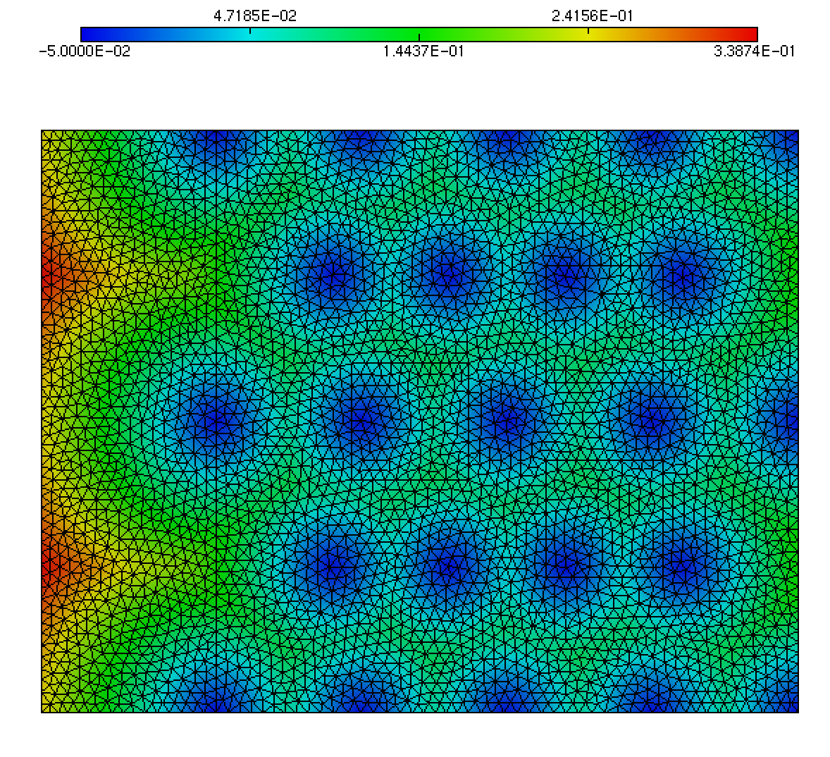
For all the examples of this page, we start from the multi-mat.mesh mesh and the discrete level-set function at the mesh nodes (multi-mat.sol file) displayed below. The left image depicts the mesh and the associated materials (element references). The right one shows the signed distance function associated to this mesh.
 |
 |
Example 1: level-set discretization
To split the domain on the 0 value of the level-set function:
mmg2d_O3 multi-mat -ls- As the solution file has the same base name than the mesh one, it is automatically loaded by Mmg (otherwise, you can provided a solution file with a different name using the -sol option).
- By default, the 0 level set is discretized. The -ls 0.1 command line argument would have discretize the 0.1 level set.
- The default mode erases the initial mesh materials (element references) to keep only the materials created by the level-set discretization (see figure 1). The multi-material mode allows to preserve both the input references and the newly created ones (see the example 3 of this page).
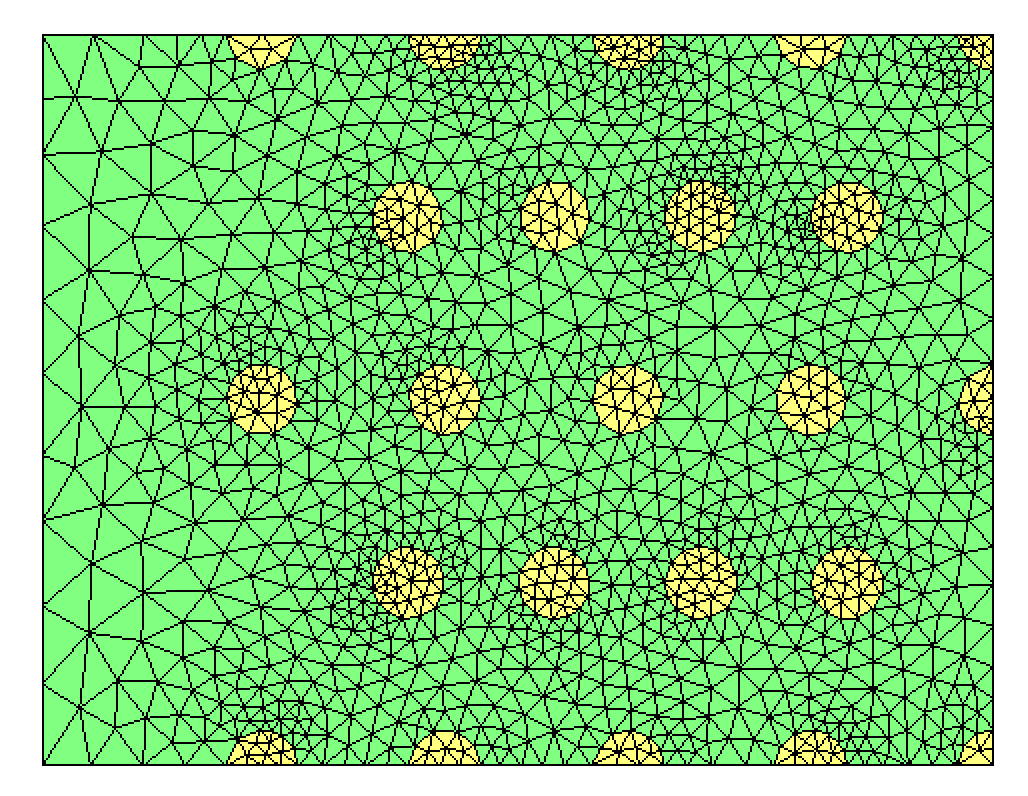
Figure 1: discretization of the 0 level-set
Example 2: Level-set discretization with size map adaptation
Given the multi-mat-met.sol file, a solution file containing metric data, you can also discretize your level-set and adapt your mesh at the same time. In that case, the metric file must be specified using the -met keyword.
mmg2d_O3 multi-mat -met multi-mat-met.sol -lsHere the metric is a constant anisotropic metric. the result is shown figure 3.
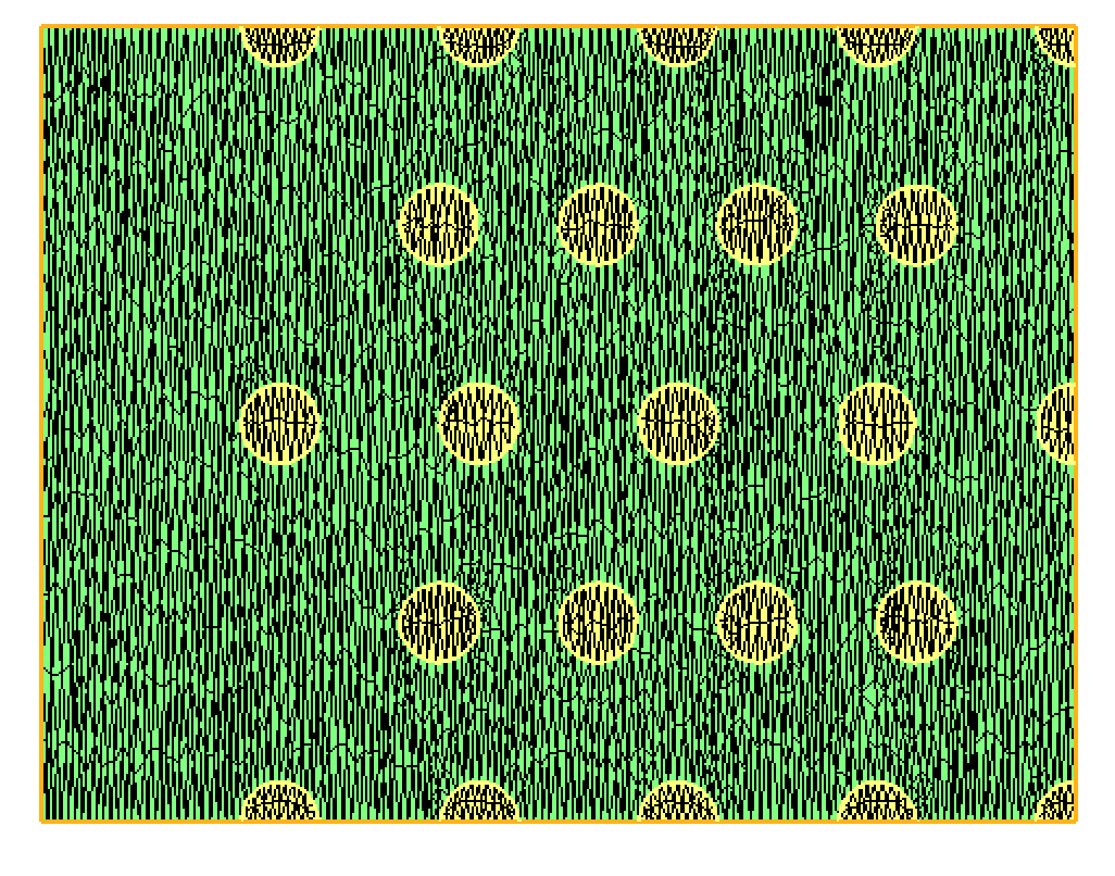
Figure 2: result of the level-set discretization with mesh adaptation on the size map provided in the multi-mat-met.sol file.
Example 3: Level-set discretization with input domains preservation
You can preserve input materials providing a multi-material file with the same name and at the same path than the mesh but with .mmg2d extension (resp .mmg3d if you use mmg3d). This file allows to specify for each input reference (or material) the values of the 2 new domains created by the level-set splitting. You can also ask to not split a given material, even if the discretized level-set pass through it.
Here, the multi-material file must be named multi-mat.mmg2d and contains the following data:
LSReferences
5
12 nosplit
14 3 2
8 21 22
0 23 24
4 25 26
It means that:
- the input domain of reference 12 (white material) will not be splitted;
- the input domain of reference 14 (pink material) will be splitted into domains 3 (yellow) and 2 (light green);
- the input domain of reference 8 (dark green) will be splitted into domains 21 (yellow) and 22 (pink);
- the input domain of reference 0 (blue top square) will be splitted into domains 23 (red) and 24 (blue);
- the input domain of reference 4 (blue bottom square) will be splitted into domains 25 (blue) and 26 (blue too);
Running the following command:
mmg2d_O3 -ls multi-matWe obtain the results depicted figure 3.
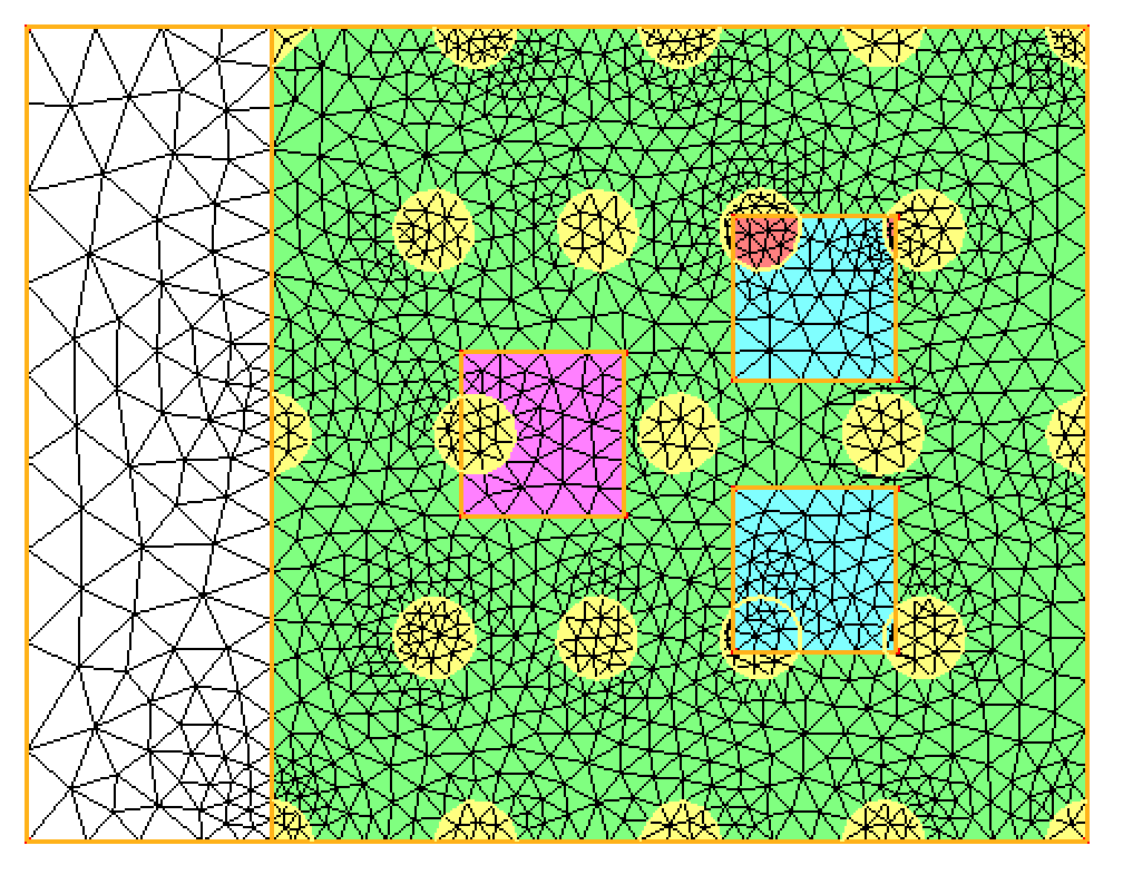
Figure 3: level-set discretization with input references (materials) preservation
Example 4: Level-set discretization with removal of small parasitic components (-rmc option)
Instead of the previous multi-mat.sol file, we will use in this example the multi-mat-rmc.sol file. The distance function is the same than the previous one except that it has been changed at point 488: the negative solution is now slightly positive. It means that the level-set 0 contains a very small bubble at point 488 (see figure 4).
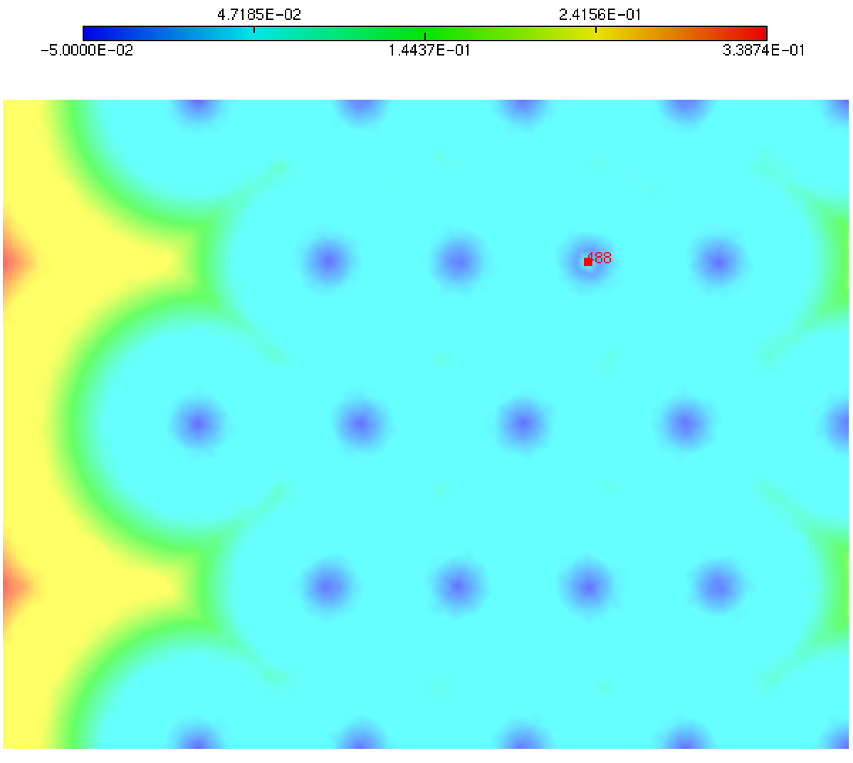
Figure 4: new distance function for which we want to discretize the 0 level-set. It contains a bubble at node 488.
By discretizing the level-set 0 using the mmg2d_O3 multi-mat.mesh -sol multi-mat-rmc.sol -ls command we obtain the mesh shown figure 5. It contains the small positive area contained within the level-set.
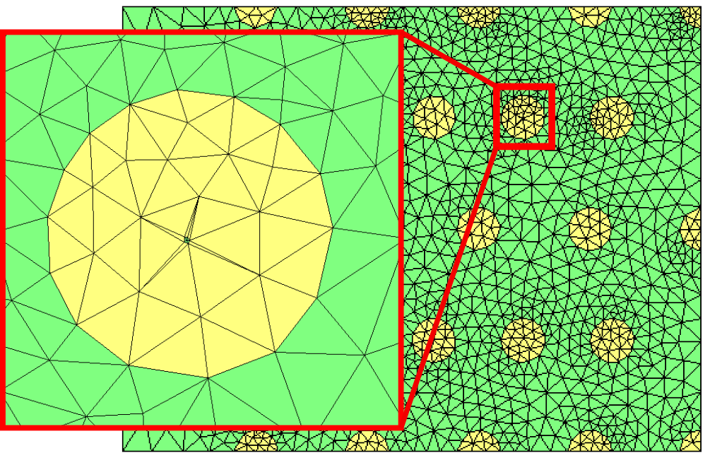
Figure 5: level-set discretization. We can see the discretization of the small positive component contained within the 0 level-set
By adding the -rmc option to the previous command line, this small parasitic component is deleted (see figure 6).
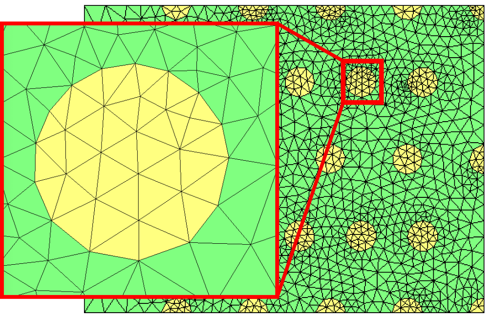
Figure 6: the rmc option allows to remove the small parasitic component.
Example 4: Boundary level-set splitting
With -lssurf option, it is possible to split only domain boundaries along the level-set while the interior of the domains is not splitted. Starting from test case of example 3 and running:
mmg2d_O3 -lssurf multi-matwe obtain the figure 7:
- Mesh boundaries are splitted (red lines)
- internal domains are not
- as no size map is provided and the mesh doesn’t contains curves (so the hausdorff doesn’t apply), the mesh is coarsened.

Figure 7: lssurf option
A multi-material maps to provide specific mapping between input references and output ones can be provided in the multi-material parameter file under the same format as for the domain references (see https://www.mmgtools.org/mmg-remesher-try-mmg/mmg-remesher-tutorials/mmg-remesher-mmgs/mmg-remesher-implicit-domain-meshing for an example). Note that if a mapping is provided for one of the input boundary references, then the mapping for all boundary references has to be given too.