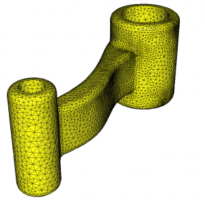
We start from a mesh named linkrods.mesh (see figure 1).

Figure 1: Initial mesh of a connecting rod
Example 1
Control the surface approximation using the -hausd option
(1) mmgs_O3 linkrods.mesh -hausd 0.01
(2) mmgs_O3 linkrods.mesh -hausd 0.001
More infos about the -hausd option
With the -hausd option, we set the hausdorff parameter that control the distance between the final triangulation and the ideal surface reconstructed from the initial triangulation. Lower is the hausdorff parameter and lower is this distance, thus better is our surface approximation. By default this value is set to 0.01 which is a suitable value for meshes whose bounding box is of size 1.
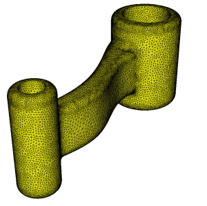
A lower hausdorff value reduces the distance between the final mesh and the ideal surface, thus, this leads to refine the mesh in curved area (compare the result of the test 1 and test 2 commands for example).
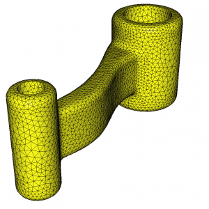
The final mesh is saved in the linkrods.o.mesh file. The result of the command (1) is displayed figure 2. and the result of the command (2) is displayed figure 3.

Figure 2: Final mesh for a hausdorff parameter of 0.01

Figure 3: Final mesh for a hausdorff parameter of 0.001
Example 2
Bound the edge sizes using the -hmin and/or -hmax options
mmgs_O3 linkrods.mesh -hmax 0.05
More infos about the -hmin/-hmax options
The
-hmin and/or
-hmax options allows to truncate the mesh at the wanted minimal and/or maximal sizes.
Here, the
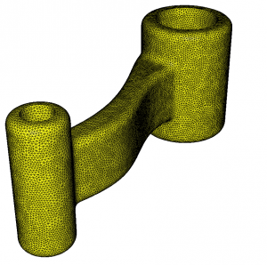
-hmax option ensure that we do not create edges longer than 0.05 (see
figure 4). In this case, the resulting mesh is quasi-uniform because without the -hmax option, almost all of the edges will be longer than 0.05.
Note that if you impose both a maximal (
-hmax) and a minimal (
-hmin) edge size, the minimal size must be strictly smaller than the maximal one (because the software need degrees of freedom to work). To impose a constant size on the whole mesh, it is advised to use a metric file (faster results and better mesh quality).

Figure 4: Final mesh for edge truncation at a maximal size of 0.05


