
Implicit domain meshing
mmg2d allows to discretize and optimize an implicitly defined surface, i.e. a surface defined by a level-set function. More information about the algorithm is available here.
For all examples on this page, the mesh
(multi-mat.mesh) and the node-defined
discrete level-set function (multi-mat.sol)
displayed below are used as input data.
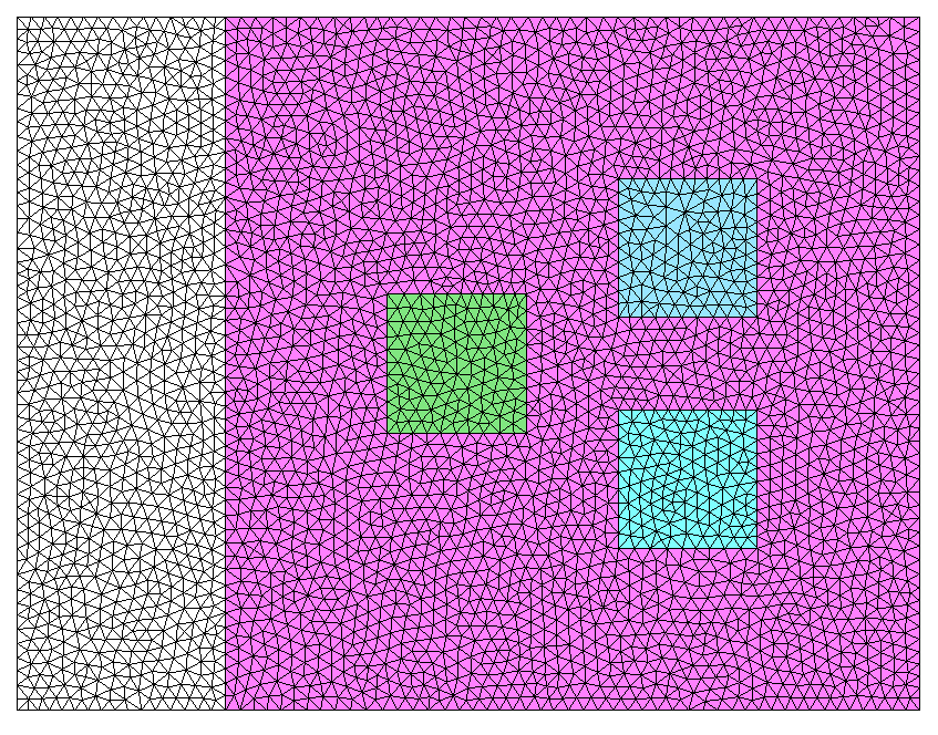
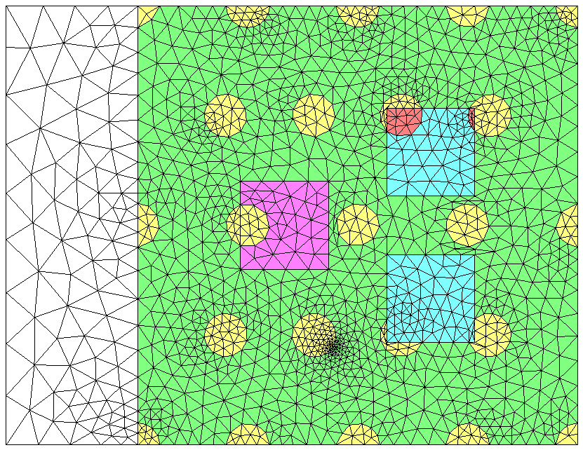
Input mesh and associated materials (element references)
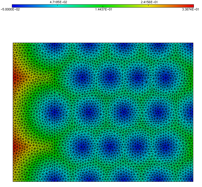
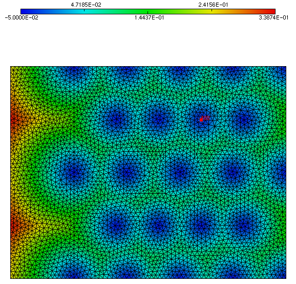
Input signed distance function
Standard level-set discretization
For the first example, the objective is to split the input mesh along the
isovalue 0 of the level-set function. To do so, run the following command:
mmg2d_O3 multi-mat -ls
As the solution file has the same base name as the mesh, it is automatically loaded by mmg. Otherwise, any solution file may be provided using the
-soloption.By default, the
0isovalue is discretized. To discretize any other isovalue, its value may be provided as an argument to the-lsoption, e.g.-ls 0.1.The default mode erases the initial mesh materials (element references) to keep the materials created by the level-set discretization, as illustrated below. The multi-material mode, presented below, allows to preserve both input and newly created references.
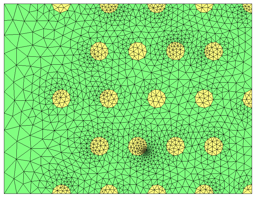
Discretization of the 0 level-set
In the output mesh, two domains (or references) are created: the subset of all
points that have a level-set value below 0 (yellow domain) and the subset of
all points that have a level-set value over 0 (green domain).
Level-set discretization with size map adaptation
Level-set discretization may be performed at the same time as mesh adaptation
with respect to a given metric. In this example, metric data is provided by the
file multi-mat-met.sol.
In ls mode, metric data must be specified using the -met keyword:
mmg2d_O3 multi-mat -met multi-mat-met.sol -ls
The metric given as an example here corresponds to a constant anisotropic metric. The output mesh is shown below.
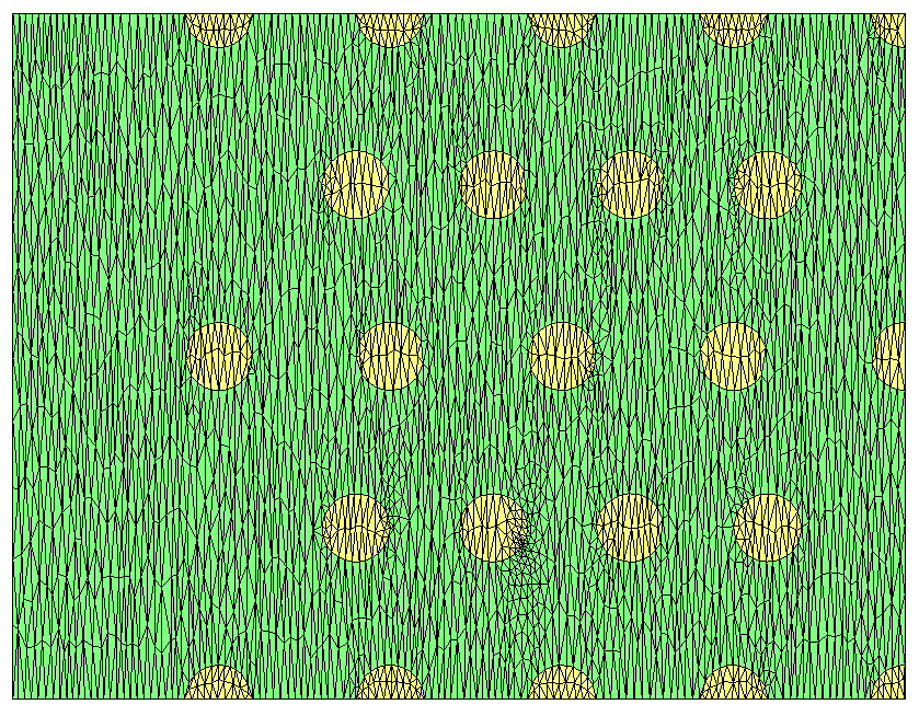
Level-set discretization with mesh adaptation.
Level-set discretization with input domain preservation
As shown in the previous example, by default, input domains are not preserved
during level-set discretization. To preserve them, it is necessary to provide a
multi-material file (.mmg2d extension) with the same name as the input mesh.
This file allows to specify, for each input reference, the values of the two new domain references created during level-set splitting. It is also possible to require for a given material not to be split, even if the discretized level-set intersects it.
In this example, the multi-material file must be called
multi-mat.mmg2d
and contains the following data:
LSReferences
5

12 nosplit
14 3 2
8 21 22
0 23 24
4 25 26
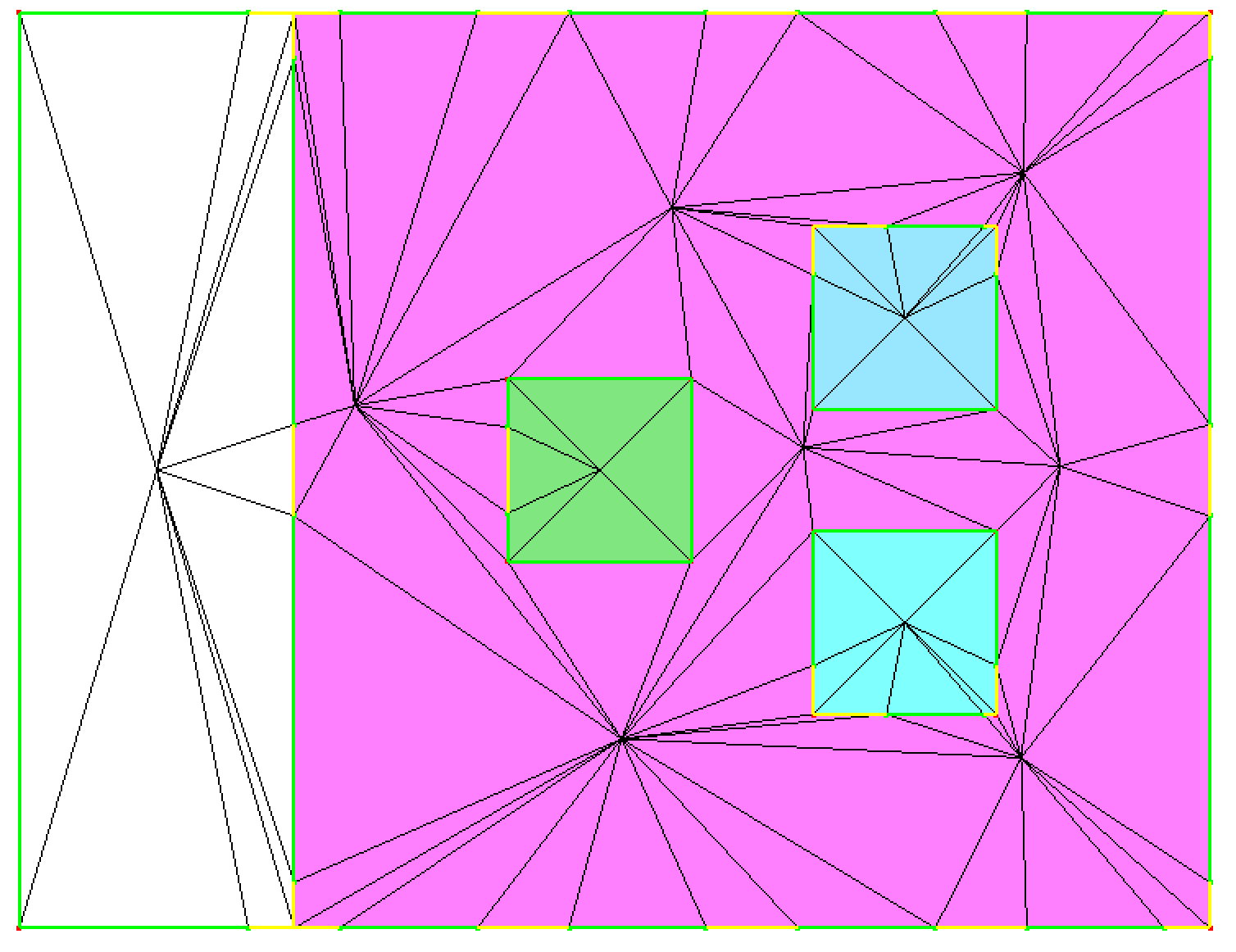
This file will be automatically detected by mmg and will enforce that:
input domain of reference 12 (white) is not split.
input domain of reference 14 (pink) is split into domains 3 (yellow) and 2 (light green).
input domain of reference 8 (dark green) is split into domains 21 (yellow) and 22 (pink).
input domain of reference 0 (blue top square) is split into domains 23 (red) and 24 (blue).
input domain of reference 4 (blue bottom square) will be split into domains 25 (blue) and 26 (blue as well).
Then, running the following command:
mmg2d_O3 -ls multi-mat
produces the output mesh displayed below.
Level-set discretization with input reference preservation
Level-set discretization with removal of small parasitic components
In this example, the solution file used is
multi-mat-rmc.sol.
The distance function is mostly the same as the previous one, but a small
component has been added in order to create a very small bubble in the output
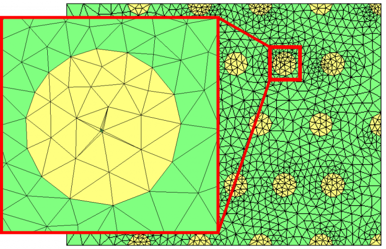
mesh. This is illustrated below.
Disturbed distance function. A small positive component is located at point 488.
To discretize the 0 level-set using the solution file, run the following
command:
mmg2d_O3 multi-mat.mesh -sol multi-mat-rmc.sol -ls
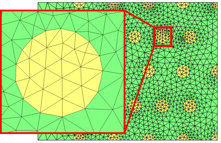
Output mesh is displayed below. It contains the small positive area contained within the level-set.
Level-set discretization with parasitic component
The -rmc option may be used to delete this parasitic component:
mmg2d_O3 multi-mat.mesh -sol multi-mat-rmc.sol -ls -rmc
Output mesh with -rmc option
The default area value for detecting a component as parasitic may be specified
as an argument to the -rmc option. The default value is set to \(10^{-5}\).
Boundary level-set splitting
It is possible to split domain boundaries along the along the level-set while
keeping domain interiors unsplit, using the -lssurf option:
mmg2d_O3 -lssurf multi-mat
Resulting mesh is shown below. Mesh boundaries are split (red lines), and internal domains are not. In this example, since no size map are provided and since the input mesh does not contain curves (meaning that so the Hausdorff criterion has no effect), the mesh is coarsened.
Output mesh with the -lssurf option
A multi-material map to provide specific mapping between input and output references can be provided in the multi-material parameter file under the same format as for the domain references. Note that if a mapping is provided for one of the input boundary references, the mapping must be given for all boundary references.