
Detailed options
-ar option
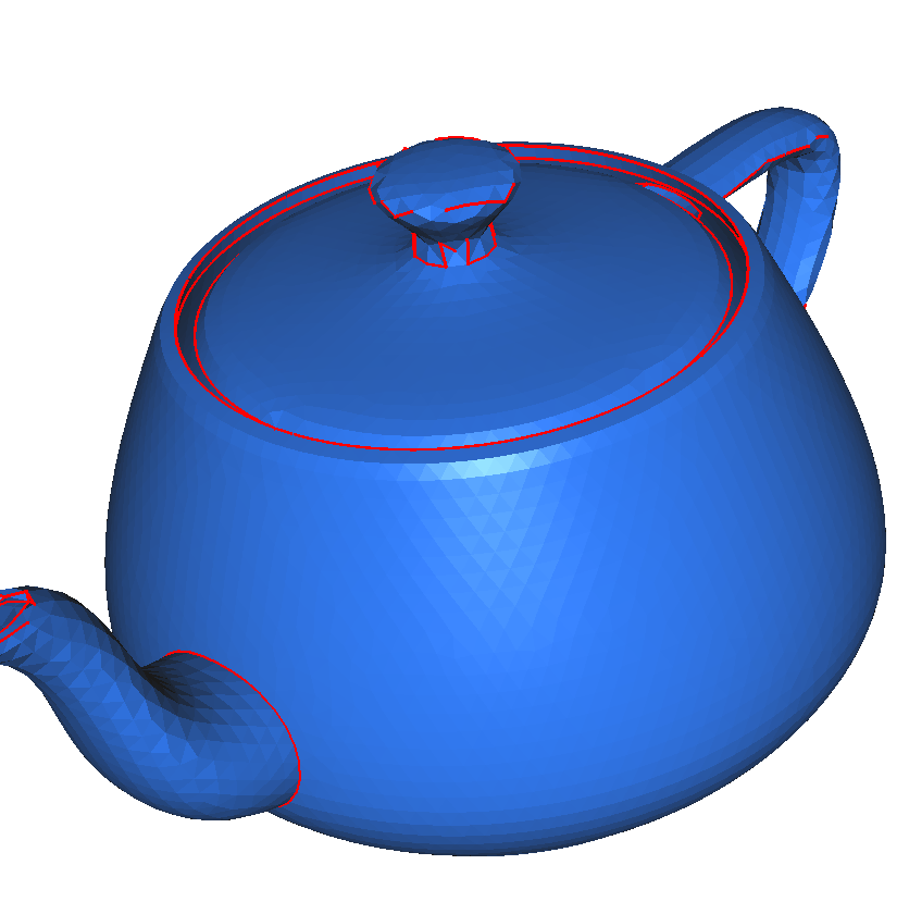
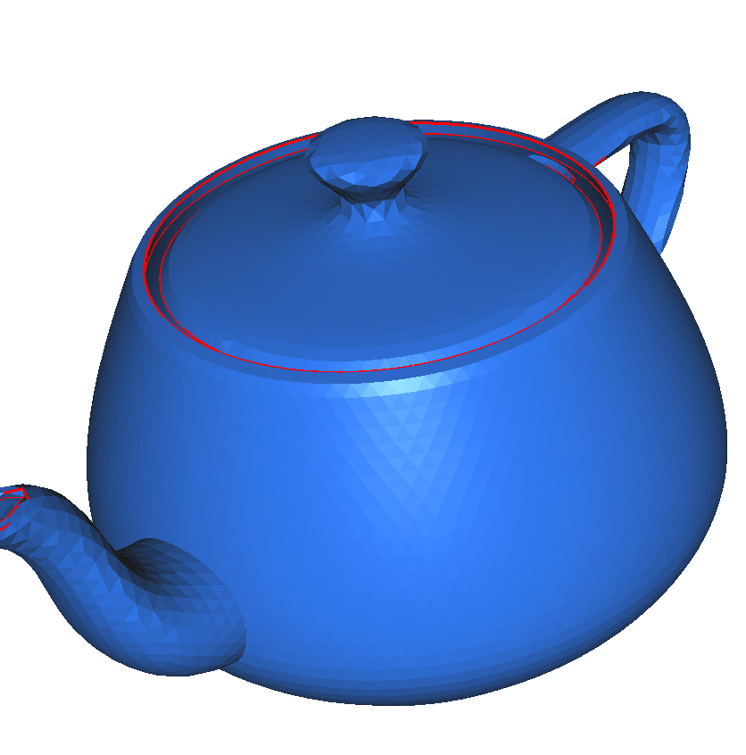
The -ar option allows to modify the value for sharp angle detection.
Default value is set to 45°. This means that a sharp angle is detected at the interface of
two boundary elements if the angle between their outward normals is greater than 45°.
For example, figure 1 represent the ridges detected by default (which is equivalent to the -ar 45 option) and figure 2 represent ridges detected by the -ar 70 option. The main differences are located at the lid handle.
-octree option
The octree is used by mmg3d to partition the mesh vertices and to speed up vertex insertion.
During the insertion step, vertices should not be inserted to close to another one. Thus, before inserting a point, we seek the octree cell to which the new point will belong and we check if it is not too close from another point of this cell or of one of the neighbouring cells.
By default, an octree cell may contain at most 64 vertices, then it is split into \(d^3\) cells (with \(d\) the mesh dimension).
You can use the -octree option to modify the maximal number of vertices per octree cell or to disable the octree (option -octree -1).
-hausd option
The -hausd option controls the boundary approximation: it enforces the maximal distance
between the piecewise linear representation of the boundary and the reconstructed ideal boundary.
Thus, a low Hausdorff parameter leads to refine the high curvature areas.
By default, the Hausdorff value is set to 0.01, which is a suitable value for an object of size 1 in each direction. for smaller (resp. larger) objects, you may need to decrease (resp. increase) the Hausdorff parameter.
Note that you can impose different Hausdorff numbers over different boundary componants using a parameter file.
-hgrad option
The hgrad option allows to set the gradation value.
It controls the ratio between two adjacent edges.
With a gradation of \(h\), two adjacent edges of length \(e_1\) and \(e_2\) must verify:
Default gradation value is 1.3.
-hmin/-hmax option
The -hmin and -hmax options allow to truncate the edge sizes to be (respectively) greater than the hmin parameter and lower than the hmax one.
The default values for these parameters are computed from the mesh bounding box or, if provided, from the given metric:
without metric data, the minimal edge size is set to 0.01 of the bounding box size. The maximal edge size is set to two times the bounding box size.
with metric data, the minimal edge size is set to 0.1 of the smallest prescribed size. The maximal one is set to 10 times the maximal prescribed size.
Note that, as the Hausdorff parameter, you can impose locally the hmin and hmax parameters using a parameter file.
-m option
The -m option allows to impose (roughly) the maximal memory size used by the mmg applications (in MB).
By default, our applications can use up to 50% of the available memory. Use the -m option to increase or decrease this amount.
For instance, to impose a maximal memory size of 2 GB, use -m 2000.
-met option
By default, mmg reads a metric file with the same name as the mesh file.
The -met option can be used to provide mesh and metric files with different names.
in adaptation mode (default mode), the
-metoption allows to provide a metric file (can be used in place of the-soloption);in level-set discretization mode, it allows to provide a metric file while the
-soloption provides level-set data;it is not used in lagrangian mode.
-optim option
The -optim option allows to preserve the initial sizes of the mesh edges in order to improve the mesh quality without modifying the edge lengths.
The prescribed size at a mesh vertex is computed (by the MMG3D_DoSol API function) as the mean of the lengths of the edges passing through this vertex.
Note that we preserve the mean of the edge lengths at vertices: thus, if the edges passing through a vertex have very different sizes, the resulting mesh may be far from the initial one.
This option is useless if you provide a sizemap with your mesh.
-sol option
By default, mmg reads a solution file with the same name as the mesh file.
The -sol option can be used to give mesh and solution files with different names.
in adaptation mode (default mode), the
-soloption allows to provide a metric file;in level-set discretization mode, it allows to provide a level-set file;
in lagrangian mode, it allows to provide a displacement file.
-v option
The -v option allows to modify software verbosity.
-v 0is the lowest verbosity. Libraries do not print anything and application print minimal information (release, copyright, building date, input and output filenames);-v 1is the default verbosity. It adds the input and output mesh qualities (minimal, maximal and mean element quality + index of the lowest quality element), a summary of the remeshing waves and informations about the output mesh (number of each entity);-v 2adds informations about edge lengths (smallest, average and largest edge length + indices of extremities of the smallest and largest edges);-v 3adds statistic informations about edge lengths;-v 4adds histograms for mesh quality and edge lengths and few analysis information;-v 5adds more detailed remeshing waves and more analysis information;-v 6print every wave of remeshing.
Parameter file
mmg applications may need the use of a parameter file to enable some specific feature.
By default, mmg3d reads a DEFAULT.mmg3d or a <meshname>.mmg3d parameter file, mmgs a DEFAULT.mmgs or a <meshname>.mmgs one and mmg2d a DEFAULT.mmg2d or a <meshname>.mmg2d parameter file (where <meshname> is the name of the input mesh without extension).
The used file format is the same for the 3 applications (see the examples below).
Local parameters assignment
You can use the parameter file to associate local Hausdorff, minimal edge size and maximal edge size to boundary references.
Note that a boundary reference refers to an integer value (a color) associated to a boundary element.
Example of local parameter assignment:
Parameters
3

38 Triangles 1.8 2.2 0.01
36 Triangles 0.098 0.12 0.1
37 Triangles 4.8 5.2 1
After the keyword “parameters”, give the number of boundary references over which you want to impose local parameters (3 in our example).
Then, for each reference, give : the reference , the type of elements on which you want to apply the parameters (for now, we just handle with the “Triangles” elements for mmgs and mmg3d and the “edges” one for mmg2d), the value of the minimal edge size, the value of the maximal one and the value of the Hausdorff parameter.
In our example, we impose:
a minimal edge size of 1.8, a maximal one of 2.2 and a Hausdorff parameter of 0.01 over all the boundary triangles of reference 38;
a minimal edge size of 0.098, a maximal one of 0.12 and a Hausdorff parameter of 0.1 over all the boundary triangles of reference 36;
a minimal edge size of 4.8, a maximal one of 5.2 and a Hausdorff parameter of 1 over all the boundary triangles of reference 37;
Note that the local parameters overwrite the global ones.
Using the API, you can set the same local parameters than in the previous example with the following calls (C):
 1/* Set the number of tags references on which you will impose local parameters*/
 2if ( MMG3D_Set_iparameter(mmgMesh,mmgSol,MMG3D_IPARAM_numberOfLocalParam,3) != 1)
 3exit(EXIT_FAILURE);
 4
 5/* For each local parameter, set the type of the entity on wich the parameter will
 6   apply (triangle or tetra), the reference of these entities and the hmin, hmax and
 7   hausdorff values to apply */
 8if ( MMG3D_Set_localParameter(mmgMesh,mmgSol,MMG5_Triangle,38,1.8,2.2,0.01) != 1)
 9exit(EXIT_FAILURE);
10if ( MMG3D_Set_localParameter(mmgMesh,mmgSol,MMG5_Triangle,36,0.098,0.12,0.1) != 1)
11exit(EXIT_FAILURE);
12if ( MMG3D_Set_localParameter(mmgMesh,mmgSol,MMG5_Triangle,37,4.8,5.2,1) != 1)
13exit(EXIT_FAILURE);
Other examples are available in the library examples of Mmg:
Multi material mode in level-set discretization mode
You can also use the parameter file to preserve input references while discretizing an isovalue. In this case, the parameter file allows to provide the material mapping between an initial material and the materials in which it will be splitted.
Note that a material corrsponds to a Mmg reference, i.e. an integer value (a color) associated to an element.
Example of materials mapping:
LSReferences
5

12 nosplit
14 3 2
8 21 22
0 23 24
4 25 26
It means that we have 5 input references (materials) and:
the input domain of reference 12 will not be splitted;
the input domain of reference 14 will be splitted into domains 3 and 2;
the input domain of reference 8 will be splitted into domains 21 and 22;
the input domain of reference 0 will be splitted into domains 23 and 24;
the input domain of reference 4 will be splitted into domains 25 and 26.
An example of use of parameter file for multi-material mode is provided in the mmg2d examples.
Using the API, you can set the same material mapping than in the previous example with the following calls (C):
 1/* Set the number of input references (materials) */
 2if ( MMG3D_Set_iparameter(mmgMesh,mmgSol,MMG3D_IPARAM_numberOfLSBaseReferences,5) != 1 )
 3exit(EXIT_FAILURE);
 4
 5/* For each material, forbid the level-set splitting or set the references
 6   of the 2 domains that are created */
 7if ( MMG3D_Set_multiMat(mmgMesh,mmgSol,12,MMG5_MMAT_NoSplit,0,0) != 1 )
 8exit(EXIT_FAILURE);
 9if ( MMG3D_Set_multiMat(mmgMesh,mmgSol,14,MMG5_MMAT_Split,3,2) != 1 )
10exit(EXIT_FAILURE);
11if ( MMG3D_Set_multiMat(mmgMesh,mmgSol,8,MMG5_MMAT_Split,21,22) != 1 )
12exit(EXIT_FAILURE);
13if ( MMG3D_Set_multiMat(mmgMesh,mmgSol,0,MMG5_MMAT_Split,23,24) != 1 )
14exit(EXIT_FAILURE);
15if ( MMG3D_Set_multiMat(mmgMesh,mmgSol,4,MMG5_MMAT_Split,25,26) != 1 )
16exit(EXIT_FAILURE);